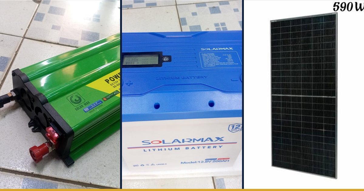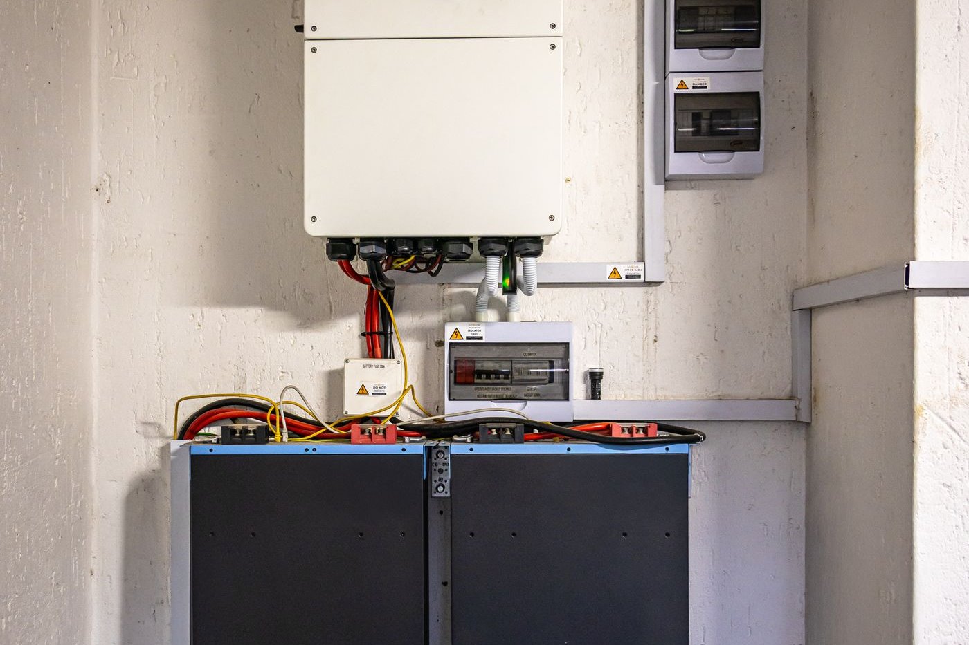

A farmer in Nyandarua buys two good panels, a new lithium battery and the cheapest charge controller in the shop. The lights work, the phone charges, and for a few weeks everything seems fine. Then the battery starts running flat by ten at night even on sunny days, and the controller gets hot enough to burn a finger. Nothing is broken. The controller simply cannot use the power the panels are making, and it was never set up for the battery it is charging.
The charge controller is the smallest and cheapest box in a solar system, and it is the one most often chosen by price alone. That is a mistake, because it decides how much of the panel's power reaches the battery, how long the battery lives, and whether the whole system is safe when a cold highland morning pushes the panel voltage up.
This guide explains what a charge controller does, the real difference between PWM and MPPT types, how to size one for amps and for volts, and how to install it so it protects the battery instead of slowly killing it. The worked examples use panels and controllers from our own price list, with every assumption stated so you can redo the sums for your system.
What a Charge Controller Actually Does
A solar panel is not a battery charger. Its voltage rises and falls with sunlight and temperature, and if it were wired straight to a battery it would keep pushing current in long after the battery was full. A charge controller sits between the panels and the battery and does three jobs.
- It charges in stages. In the bulk stage it passes as much current as the panels can give. Near full it holds the battery at a set absorption voltage while the current tapers off. Then it drops to a lower float voltage, or stops, depending on the battery chemistry.
- It stops overcharging. Overcharging boils the water out of a flooded lead acid battery and can trip the protection circuit, or worse, on a lithium battery.
- It protects against over-discharge on controllers with load terminals: when the battery falls to a set voltage, the load output switches off. This is called a low voltage disconnect.
Most controllers also block current flowing back from the battery to the panels at night. What separates one controller from another is how efficiently it moves power from panel to battery, and that is where PWM and MPPT differ.
PWM and MPPT: Where the Difference Comes From
A PWM (pulse width modulation) controller is essentially a fast electronic switch. When charging, it connects the panel directly to the battery, so the panel is forced to work at roughly the battery's voltage. The panel's current passes through, but any spare voltage is simply not used.
That matters because a panel sold for 12 V systems is built to work at a higher voltage than the battery, so it can still charge on a hot afternoon. Read the label on the back of the panel: it gives the maximum power voltage (Vmp) and current (Imp). On a PWM controller, the battery only gets roughly Imp multiplied by the battery's charging voltage, and the gap between that and the panel's rated watts is lost.
An MPPT (maximum power point tracking) controller contains a DC to DC converter. It keeps searching for the voltage at which the panel gives the most power, runs the panel there, then converts the higher voltage down to battery voltage while raising the current. Most of the panel's power reaches the battery, minus the converter's own small losses.
The gap is not fixed. It is smallest when the panel's working voltage sits just above the battery's, and it grows when the panel voltage is much higher than the battery voltage. In cool, bright conditions, when the panel voltage is at its highest, an MPPT controller has the most to gain. On a very hot iron roof, the panel voltage sags and the two types come closer together.
When a PWM Controller Is the Right Answer
PWM is not a bad technology. It is simple, cheap and reliable, and for a small system it is often the sensible choice. It fits best when three things are true:
- The system is small: one or two panels of around 100 W or less, lighting a house, charging phones and running a radio.
- The panels are of the type made for 12 V batteries (the ones on our list marked 18V, such as the 60 W, 80 W and 100 W panels), so the voltage match is close.
- The money saved is better spent on panel or battery capacity than on a more expensive controller.
For a small system, an extra panel often buys more energy than the difference between PWM and MPPT would recover. Once the array grows past a couple of hundred watts, or the panels are the large high-voltage type sold for bigger systems, the sums swing firmly towards MPPT.
Sizing for Amps: the Current Rating
The number on a controller, such as 20 A or 40 A, is the maximum charging current it can handle. It is sized differently for the two types.
For PWM, the controller passes the panel current straight through, so its rating must exceed the array's short circuit current (Isc, printed on the panel label). A common safety margin is to multiply Isc by 1.25, because on a bright day with reflection off clouds a panel can briefly give more than its label current. With panels in parallel, add their Isc values first.
For MPPT, the controller's rating is its output current to the battery. Divide the array's rated watts by the battery voltage to get the most it could deliver, then choose a controller at or above that figure.
- Two PANEL 200 W/24V panels, 400 W, on a 12 V battery: 400 ÷ 12 ≈ 33 A. A 40 A MPPT controller fits; a 30 A unit would clip the output on the best hours of the day.
- The same 400 W on a 24 V battery: 400 ÷ 24 ≈ 17 A. A 20 A MPPT controller is enough.
- One PANEL 100W/18V on a 12 V battery with PWM: if the label Isc is, say, 6 A, then 6 × 1.25 = 7.5 A, comfortably within a 20 A controller with room to add a second panel later.
Notice the second example. Moving from a 12 V to a 24 V battery bank halves the current for the same power, which means a smaller controller, thinner cables and less heat. For anything above a few hundred watts, a 24 V system is usually the better design. Our guide to sizing an inverter for a farm or workshop explains the same logic from the inverter's side.
Sizing for Volts: the Cold Morning Check
An MPPT controller also has a maximum input voltage from the panels, and this is the limit people forget. Exceeding it, even briefly, can destroy the controller, and many makers' warranties exclude that damage.
The figure to check is the open circuit voltage (Voc) on the panel label, which is what the panel shows with nothing connected. Panels wired in series add their Voc together. Panel voltage also rises as the cells get colder, so the highest voltage of the year comes at sunrise on the coldest morning, before the panels warm up. In Kenya's highlands, from Timau to Nyandarua and the Mau, clear dawns can be close to freezing, and that is when a string that looked safe on paper goes over the limit.
The method is simple: add up the Voc of every panel in the series string, add a margin for cold (the panel data sheet gives a temperature coefficient; without it, many installers allow somewhere around 10 to 15 percent in cool climates), and make sure the result stays below the controller's maximum PV input voltage. If it does not, rewire some panels in parallel or choose a controller with a higher input limit.
Match the Controller to the Battery
A controller charges to set voltages, and those voltages must suit the battery. Lead acid batteries want an absorption stage and a float, and flooded types benefit from an occasional equalisation charge. Lithium batteries want different voltages and no equalisation at all; a lead acid profile can trip a lithium battery's protection or shorten its life.
Before you buy, confirm that the controller has a lithium setting if you are using a lithium battery such as our 100 Ah lithium battery, or that its voltages can be set by hand to the figures on the battery's data sheet. Older and cheaper PWM units are often fixed to lead acid. Our comparison of lithium and lead acid solar batteries covers the charging differences in detail.
If you are buying a hybrid inverter, check whether it already has a solar charger built in, because most do. In that case you may not need a separate controller at all, but the same questions apply to the built-in one: PWM or MPPT, maximum current, maximum input voltage, and battery settings.
Installing It So It Lasts
Most controller failures are installation faults rather than bad units. These habits avoid most of them, and a qualified electrician will follow them as a matter of course.
- Connection order. Most makers say: battery first, so the controller can detect the system voltage, then the panels, then any loads. Disconnect in the reverse order. Follow your controller's manual where it differs.
- Fuse the battery cable. Fit a fuse or DC breaker rated for the controller's current in the positive cable, close to the battery. A battery can deliver a very large current into a short circuit, enough to melt cable and start a fire.
- Short, thick battery cables. Mount the controller close to the battery. A long, thin cable makes the controller read the wrong voltage and undercharge.
- Keep it cool and dry. Controllers shed heat through their casing. Mount on a wall with space around it, out of direct sun, and never inside a sealed box with flooded lead acid batteries, which give off hydrogen when charging.
- Inverters go on the battery, not the load terminals. The load terminals on small controllers are rated for a few amps of lights and phone chargers. An inverter draws far more, so it connects directly to the battery through its own fuse.
Once installed, check the controller's display or lights on a sunny morning and again in the evening for the first week. You should see the battery reach full charge on a good day. If it never does, the array is too small for your loads, the controller is clipping, or the battery settings are wrong. Our guide to solar performance in the rainy season explains what to expect when the short rains bring cloudy weeks.
Choosing From Our Range
These are the controllers, panels and battery from our price list used in the examples above. Ask us to confirm whether a given controller is PWM or MPPT, its maximum input voltage and whether it has a lithium setting before you buy, because those three details decide whether it suits your panels and battery.
| Item | Stock code | Price |
|---|---|---|
| CHARGE CONTROLLER 20 AMPS | 6835 | 1,200 KSH |
| CHARGE CONTROLLER | 6459 | 2,500 KSH |
| CHARGE CONTROLLER 30A | 6152 | 3,000 KSH |
| CHARGE CONTROLLER 40A | 6153 | 4,000 KSH |
| PANEL 100W/18V | 6313 | 5,000 KSH |
| PANEL 200 W/24V | 6314 | 11,000 KSH |
| 100 AMPS LITHIUM BATTERY | 6833 | 19,000 KSH |
The 20 A charge controller has its own product page. If you are still working out how many panels and how much battery you need, start with our guide to solar panel sizing and budget, then come back to choose the controller to match.
A sensible rule of thumb: for a small 12 V lighting system of one or two 18 V panels, a correctly rated PWM controller does the job. For anything larger, for panels of 24 V and above, or for long cable runs from a roof or a pump site, budget for MPPT. And whichever you choose, leave a little headroom in the current rating so that one more panel next year does not mean a new controller.
Bring us the labels from your panels and battery, at any Fuga branch or on WhatsApp 0716 961 018, and we will work through the amps and the cold morning voltage with you and match the controller to your system. The full range is on our solar equipment page.
Key Takeaways
- A charge controller charges the battery in stages, stops overcharging and, on models with load terminals, cuts loads off before the battery runs too low.
- A PWM controller pulls the panel down to battery voltage, so it suits small systems with 18 V panels on a 12 V battery; larger or higher-voltage panels need MPPT.
- Size a PWM controller at the array's short circuit current times 1.25, and an MPPT controller at the array watts divided by the battery voltage.
- Add the open circuit voltage of every panel in a series string, allow a margin for cold highland mornings, and keep the total below the controller's maximum input.
- Match the charging profile to the battery: a lithium battery needs a lithium setting or hand-set voltages from its data sheet.
- Mount the controller close to the battery in a cool, ventilated spot, fuse the battery cable, and connect inverters to the battery rather than the load terminals.
Frequently Asked Questions
Is MPPT worth the extra cost over PWM?
For a small 12 V system with one or two 18 V panels, a correctly rated PWM controller is usually enough, and the money saved can buy more panel or battery. For arrays above a couple of hundred watts, panels rated 24 V or more, or long cable runs, MPPT recovers far more of the panel's power and is worth it.
What size charge controller do I need for a 400 watt array?
For an MPPT controller, divide the array watts by the battery voltage. As a worked example, 400 W on a 12 V battery is about 33 A, so a 40 A controller fits; the same 400 W on a 24 V battery is about 17 A, so a 20 A controller is enough. Also check the controller's maximum input voltage against the panels' open circuit voltage.
Can I use a lead acid charge controller with a lithium battery?
Only if its charging voltages can be set to the figures on the lithium battery's data sheet. A fixed lead acid profile, especially one with equalisation charging, can trip the battery's protection or shorten its life. Choose a controller with a lithium setting where possible.
Why does my charge controller get very hot?
Warm is normal on a sunny afternoon. Too hot to touch usually means the controller is undersized for the panels, mounted where air cannot reach it, or working through a loose, high-resistance connection. Switch off the panels and battery, then have the size, mounting and connections checked.
Can I connect my inverter to the controller's load terminals?
No. The load terminals on most small controllers are rated for a few amps of lights and phone chargers. An inverter draws far more current, so it should be connected directly to the battery through its own correctly rated fuse, ideally by a qualified electrician.